ESP8266 is a Wifi Module which is
small in size and very useful for IoT (Internet of Things) Projects usingArduino. Here we are describing the how to interface ESP8266 Module with
Arduino. Here we are the interfacing circuit as Module with PCB and design
created in Proteus right now.
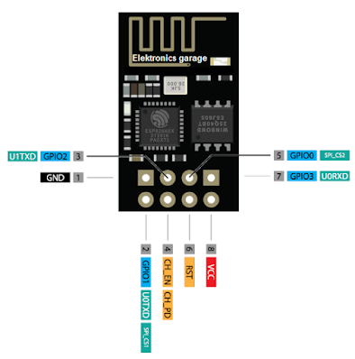
Here is the pinout of ESP8266
Module:
|
PIN |
Description |
|
1 |
GND |
|
2 |
GPIO1 / U0TXD / SPI_CS1 (Connect with RX of Arduino) |
|
3 |
GPIO2 |
|
4 |
CH_PD / CH_EN (Connect with 3.3v to enable the Module for Communication) |
|
5 |
GPIO0 / SPI_CS2 (Use jumper with GND to Program ESP8266
Module GPIOs) |
|
6 |
RESET (Hard reset use push button here to reset the ESP8266 module) |
|
7 |
GPIO3 / U0RXD (Connect with TX of Arduino) |
|
8 |
Vcc (Connect with 3.3v of Arduino) |
Circuit Diagram:
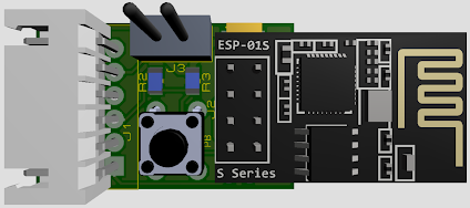
PCB 3D Design front:
PCB 3D Design front:
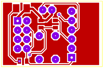
PCB Layout front:
PCB Layout Back:


( ' , ' ) Nice information shared
ReplyDelete