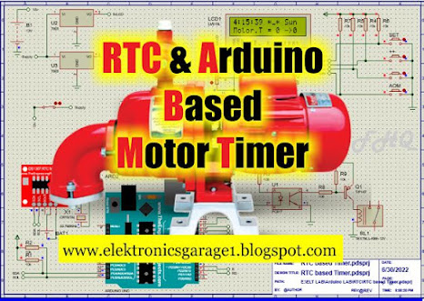
Hi after a long time I am here with a timer for you which's very useful for home appliances as you can see in title.
In daily life we analyze that some appliances are helping in human life to overcome the human efforts and struggles like water pump, washing machines refrigerator's etc. but we also concern with utilization of power as well. So we want to manage these things in a good and desire manners.
So here is a Arduino and real time clock RTC based adjustable timer for your appliance. You Just set you desire minutes to ON the appliance in each hour then save that. Than you will be feel easy.
This Circuit is especially design for water pump to suck the water from the ground after each hour.
Function buttons:
set: Press to enter in setting mode for timer ON and OFF minutes, Real time setting, Day setting then saving that values
++ : is use to increase values
-- : is use to decrease values
AOM : is empty right now for one more advancement I want to do (I will share in next version)
Components used:
- Arduino Uno
- RTC (DS1307)
- LCD 16x2
- Push button
- 7805 Regulators
- SPDT Relay 12v operated
- TIP147
- Optocoupler 817
- Resistors 10k, 220
- Pot-meter 5k for Contrast control with LCD
- 12v adopter 2A
- Li cell for RTC
You can get all the components online from Electronics world by just clicking here
Circuit diagram: Proteus file
Arduino program:
// RTC and Arduino based Motor timer //
//  FHQ Design, 30 July,2022         //
//www.elektronicsgarage1.blogspot.com//

// Date and time functions using a DS1307 RTC connected via I2C and Wire lib
#include
#include
#include "RTClib.h"

RTC_DS1307 rtc;
const int rs = 2, en = 3, d4 = 4, d5 = 5, d6 = 6, d7 = 7;
LiquidCrystal lcd(rs, en, d4, d5, d6, d7);
//RTC_DS1307 RTC;

//************Button*****************//
int Bset  =8; // Button SET MENU'
int Binc  =9; // Button +
int Bdec  =10; // Button -
int Baom  =11; // Auto or Manual
int motor =12; // motor control pin
int LED   =13;   // led


 //void now_time();
int manu=0,hr=0,mint=0,mintcheck=0,On_time=3,daycheck=0;
int ONt,OFFt;
int yearm, monthm, daym=daym+2, hourm=12, minutem=12, secm=12;
char daysOfTheWeek[7][12] = {"Sun   ", "Mon   ", "Tue    ", "Wed      ", "Thu     ", "Fri   ", "Sat     "};
//#define label;
void setup ()
{
  lcd.begin(16,2);
  lcd.clear();
  Serial.begin(9600);
  while (!Serial) {
    ; // wait for serial port to connect. Needed for native USB port only
  }
  Serial.println("Goodnight moon!");

  pinMode(Bset,INPUT);
  pinMode(Binc,INPUT);
  pinMode(Bdec,INPUT);
  pinMode(Baom,INPUT);
  pinMode(LED,OUTPUT);
  pinMode(LED, OUTPUT); // Set buzzer as an output
  pinMode(motor, OUTPUT);
  digitalWrite(motor, HIGH);
  Wire.begin();
//  RTC.begin();
  //Serial.begin(9600);

  if (! rtc.begin())
  {
    lcd.print("Couldn't find RTC");
    while (1);
  }

  if (! rtc.isrunning())
  {
    lcd.print("RTC is NOT running!");
  }

   rtc.adjust(DateTime(F(__DATE__), F(__TIME__)));//auto update from computer time
  // rtc.adjust(DateTime(yearm, monthm, daym, hourm, minutem, secm));// to set the time manualy
  //setTime(varHr, varMin, varSec, vardd, varmm, varyy);
}

void loop ()
{
  // Function Modes changing //
  //delay(10);
  //int sw = digitalRead(Bset);delay(100);
  if (digitalRead(Bset) == LOW){
  //for (int x=0;x<=1000;x++){}
  delay(500);manu++;
  //lcd.print("Function #");
  //lcd.print(manu);
   if (manu>6){
    manu=0;}
  }

  // Functions //

    if (manu==0){
    now_time();
    setmotor();
   delay(10);
   }
//label:
    if (manu==1){
      motor_ONtime();}

    if (manu==2){
      motor_OFFtime();}

    if(manu==3){
      sethr_T();}

    if(manu==4){
      setmin_T();}

     if(manu==5){
      setday_w();}

    if(manu==6){
    Save_Prog();}
}
    void now_time()
    {
    DateTime now = rtc.now();

    lcd.setCursor(0, 0); // 12:45:78 * * mon

    /* Serial.print(now.hour());
     Serial.print(":");
     Serial.print(now.minute());
     Serial.print(":");
      Serial.print(now.second());
     Serial.println();*/

    lcd.print(now.hour());
    hr=now.hour();
    lcd.print(':');
    lcd.print(now.minute());
    mint = now.minute();
    mintcheck=now.minute();
    lcd.print(':');
    lcd.print(now.second());
    lcd.print(" *_* ");
    lcd.print(daysOfTheWeek[now.dayOfTheWeek()]);
    daym=now.dayOfTheWeek();
   // daym=daym-2;
    //lcd.setCursor(0, 1);
   // lcd.print("                ");
    delay(10);
    }
    /*
    lcd.setCursor(0, 1);
    lcd.print(now.day());
    lcd.print('/');
    lcd.print(now.month());
    lcd.print('/');
    lcd.print(now.year());
   */

   void setmotor(){ // 0
     lcd.setCursor(0, 1);
   lcd.print("Motor.T =   ->  ");
   lcd.setCursor(10, 1);
   lcd.print(ONt, DEC);
   lcd.setCursor(14, 1);
   lcd.print(OFFt, DEC);

   if ((ONt<= mintcheck)&&(mintcheck60){lcd.setCursor(11, 1);lcd.print("(^_^)");delay(1000);OFFt=0;}}
           if (digitalRead(Bdec)== LOW)
                {delay(500);OFFt--;
                if (OFFt<0 0="" 1="" 3="" delay="" digitalread="" hours="" hr="" if="" inc="" lcd.print="" lcd.setcursor="" low="" motor="" n_time="OFFt;" set="" sethr_t="" t="60;}}//" time="" void="">24){lcd.setCursor(10, 1);lcd.print("(^_^)");delay(1000);hr=1;}}
           if (digitalRead(Bdec)== LOW)
                {delay(500);hr--;
                if (hr<0 1="" delay="" digitalread="" hr="24;}}" if="" inc="" lcd.print="" lcd.setcursor="" low="" mint="" minute="" ours=");
   lcd.setCursor(10, 1);
   lcd.print(hr);
   //now.hour()=hr;
   delay(10); }

   void setmin_T(){ // 4
      lcd.setCursor(0, 0);
   lcd.print(" set="" time="">60){lcd.setCursor(11, 1);lcd.print("(^_^)");delay(1000);mint=1;}}
           if (digitalRead(Bdec)== LOW)
                {delay(500);mint--;
                if (mint<0 1="" day="" daycheck="" daym="" delay="" digitalread="" if="" inc="" inute=");
   lcd.setCursor(11, 1);
   lcd.print(mint);
   delay(10); }

  void setday_w(){ // 5
   //int mint;
   lcd.setCursor(0, 0);
   lcd.print(" lcd.print="" lcd.setcursor="" low="" mint="24;}}" set="" week="">6){lcd.setCursor(10, 1);lcd.print("(^_^)");delay(1000);daym=0;}}
           if (digitalRead(Bdec)== LOW)
                {delay(500);daym--;
                if (daym<0 0="" 1="" atetime="" ay=");
   lcd.setCursor(10, 1);
  lcd.print(daysOfTheWeek[daym]);       // sun mon tue wed thu fri sat
   delay(10); }                         //  0   1   2   3   4   5   6
                                        //  2   3   4   5   6   0   1
   void Save_Prog(){ // 6
   lcd.setCursor(0, 0);
   lcd.print(" data="" daym="" delay="" hourm="" if="" lcd.print="" lcd.setcursor="" manu="0;" manualy="" minutem="" monthm="" otor.t="-" rtc.adjust="" saving="" secm="" set="" t="" the="" time="" to="" wait="" yearm="">  ");
                lcd.setCursor(10, 0);
                lcd.print(ONt, DEC);
                lcd.setCursor(14, 0);
                lcd.print(OFFt, DEC);
                lcd.setCursor(0, 1);
                lcd.print("Error::OFFt>ONt");
                delay(1000);
                manu=1;
                }

  // On_time = ONt;
  delay(1000);  }
If you like my project ! Plz share it and comment me
Thanks