
What is logic?

In
digital we define some conditions of anything in two states that are 0 and 1
for example switch conditions possibly open and close so in digital it will be 0 and 1 respectively Same as
down up, left-right, off ON and false true, etc.

NOT Logic Gate
NOT Gate
performs the function to invert the logic. If the input is 0 then the output will be 1
and if the input is 1 then the output will be 0.
Symbol of NOT Logic Gate

Truth Table
we can understand the NOT (inverter) function by a simple electrical circuit.

 S1 close LED will be OFFS1 open LED will be ON

RTL of NOT Gate

by using the switching mode of the transistor to understand the
working of RTL NOT gate.
working
of RTL NOT gate.
Input 0: Q1 will
be in off condition and current flow toward output through R1 means output 1.
Input 1: Q1 will be ON and current flow through Q1 and R1 and ground. Max voltage drop across R1. (VCE = VCC – ICRC) and the output will be 0.
CMOS (basic circuit is) NOT gate
CMOS
is Complementary to MOS which means in this logic NMOS and PMOS twice are used. CMOS
basic circuit is NOT gate.
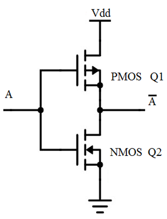
If input
A=0:
When input A=0 then PMOS will be ON and NMOS will be OFF and the current flows through output so output logic = 1.
If input
A=1:
When input A = 1 then PMOS will be OFF and NMOS will be off Now current flow through PMOS and output so the output is 0.


No comments:
Write commentsI am very thankful for your precious time