Showing posts with label Arduino. Show all posts

Saturday, October 14, 2023

ESP8266 Module Interface with Arduino


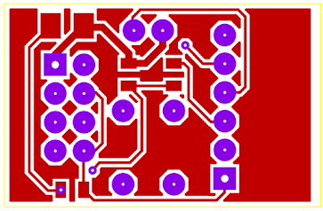
ESP8266 is a Wifi Module which is small in size and very useful for IoT (Internet of Things) Projects usingArduino. Here we are describing the how to interface ESP8266 Module with Arduino. Here we are the interfacing circuit as Module with PCB and design created in Proteus right now.

Here is the pinout of ESP8266 Module:

ESP8266 Pinout

PIN

Description

1

GND

2

GPIO1 / U0TXD / SPI_CS1 (Connect with RX of Arduino)

3

GPIO2

4

CH_PD / CH_EN (Connect with 3.3v to enable the Module for Communication)

5

GPIO0 / SPI_CS2 (Use jumper with GND to Program ESP8266 Module GPIOs)

6

RESET (Hard reset use push button here to reset the ESP8266 module)

7

GPIO3 / U0RXD (Connect with TX of Arduino)

8

Vcc (Connect with 3.3v of Arduino)

Circuit Diagram:


PCB 3D Design front:

ESP8266 Module Design

PCB 3D Design front:

ESP8266 Module Design

PCB Layout front:

ESP8266 Module PCB Layout

PCB Layout Back:

ESP8266 Module PCB Layout

If you like my post, then click like and comment and share it please.

If you want Gerber file then Comment here.


Read More

Saturday, April 29, 2023

Different types of Arduino Boards


Types of Arduino Boards

Arduino 

                is prototype open source platform which’s consist on little hardware and very easy software called Arduino IDE (Integrated Development Environment). It’s very easy to use, perform, test and program your logics by using Arduino setup.

                    Here we are sharing specifications of different types of Arduino Boards so that you can select Arduino Board according to your Arduino projects requirements. 

Types of Arduino Boards

Useful links:

Read More

Sunday, July 17, 2022

RTC and Arduino Based Adjustable Motor Timer

RTC and Arduino Based Adjustable Motor Timer
Hi after a long time I am here with a timer for you which's very useful for home appliances as you can see in title.

In daily life we analyze that some appliances are helping in human life to overcome the human efforts and struggles like water pump, washing machines refrigerator's etc. but we also concern with utilization of power as well. So we want to manage these things in a good and desire manners.

So here is a Arduino and real time clock RTC based adjustable timer for your appliance. You Just set you desire minutes to ON the appliance in each hour then save that. Than you will be feel easy.

This Circuit is especially design for water pump to suck the water from the ground after each hour.

Function buttons:

set: Press to enter in setting mode for timer ON and OFF minutes, Real time setting, Day setting then saving that values

++ : is use to increase values

-- : is use to decrease values

AOM : is empty right now for one more advancement I want to do (I will share in next version)

Components used:

  •     Arduino Uno
  •     RTC (DS1307)
  •     LCD 16x2
  •     Push button
  •     7805 Regulators
  •     SPDT Relay 12v operated
  •     TIP147
  •     Optocoupler 817
  •     Resistors 10k, 220
  •     Pot-meter 5k for Contrast control with LCD
  •     12v adopter 2A
  •     Li cell for RTC
You can get all the components online from Electronics world by just clicking here

Circuit diagram: Proteus file

RTC and Arduino Based Adjustable Motor Timer

Arduino program:

// RTC and Arduino based Motor timer //
//  FHQ Design, 30 July,2022         //
//www.elektronicsgarage1.blogspot.com//
 
// Date and time functions using a DS1307 RTC connected via I2C and Wire lib
#include 
#include 
#include "RTClib.h"

RTC_DS1307 rtc;
const int rs = 2, en = 3, d4 = 4, d5 = 5, d6 = 6, d7 = 7;
LiquidCrystal lcd(rs, en, d4, d5, d6, d7);
//RTC_DS1307 RTC;

//************Button*****************//
int Bset  =8; // Button SET MENU'
int Binc  =9; // Button +
int Bdec  =10; // Button -
int Baom  =11; // Auto or Manual
int motor =12; // motor control pin
int LED   =13;   // led


 //void now_time();
int manu=0,hr=0,mint=0,mintcheck=0,On_time=3,daycheck=0;
int ONt,OFFt;
int yearm, monthm, daym=daym+2, hourm=12, minutem=12, secm=12;
char daysOfTheWeek[7][12] = {"Sun   ", "Mon   ", "Tue    ", "Wed      ", "Thu     ", "Fri   ", "Sat     "};
//#define label;
void setup () 
{
  lcd.begin(16,2);
  lcd.clear();
  Serial.begin(9600);
  while (!Serial) {
    ; // wait for serial port to connect. Needed for native USB port only
  }
  Serial.println("Goodnight moon!");
  
  pinMode(Bset,INPUT); 
  pinMode(Binc,INPUT);
  pinMode(Bdec,INPUT);
  pinMode(Baom,INPUT);
  pinMode(LED,OUTPUT);
  pinMode(LED, OUTPUT); // Set buzzer as an output
  pinMode(motor, OUTPUT);
  digitalWrite(motor, HIGH);  
  Wire.begin();
//  RTC.begin();
  //Serial.begin(9600);
   
  if (! rtc.begin()) 
  {
    lcd.print("Couldn't find RTC");
    while (1);
  }

  if (! rtc.isrunning()) 
  {
    lcd.print("RTC is NOT running!");
  }
  
   rtc.adjust(DateTime(F(__DATE__), F(__TIME__)));//auto update from computer time
  // rtc.adjust(DateTime(yearm, monthm, daym, hourm, minutem, secm));// to set the time manualy 
  //setTime(varHr, varMin, varSec, vardd, varmm, varyy);
}

void loop () 
{
  // Function Modes changing //
  //delay(10);
  //int sw = digitalRead(Bset);delay(100);
  if (digitalRead(Bset) == LOW){
  //for (int x=0;x<=1000;x++){}
  delay(500);manu++;
  //lcd.print("Function #");
  //lcd.print(manu);
   if (manu>6){
    manu=0;}
  }

  // Functions //
  
    if (manu==0){
    now_time();
    setmotor();
   delay(10);
   }
//label:   
    if (manu==1){
      motor_ONtime();}

    if (manu==2){
      motor_OFFtime();}
      
    if(manu==3){
      sethr_T();} 
    
    if(manu==4){
      setmin_T();}

     if(manu==5){
      setday_w();}
      
    if(manu==6){
    Save_Prog();}
}
    void now_time()
    {
    DateTime now = rtc.now();
    
    lcd.setCursor(0, 0); // 12:45:78 * * mon
    
    /* Serial.print(now.hour());
     Serial.print(":");
     Serial.print(now.minute());
     Serial.print(":");
      Serial.print(now.second());
     Serial.println();*/
    
    lcd.print(now.hour());
    hr=now.hour();
    lcd.print(':');
    lcd.print(now.minute());
    mint = now.minute();
    mintcheck=now.minute();
    lcd.print(':');
    lcd.print(now.second());
    lcd.print(" *_* ");
    lcd.print(daysOfTheWeek[now.dayOfTheWeek()]);
    daym=now.dayOfTheWeek();
   // daym=daym-2;
    //lcd.setCursor(0, 1);
   // lcd.print("                ");
    delay(10);
    }
    /*
    lcd.setCursor(0, 1);
    lcd.print(now.day());
    lcd.print('/');
    lcd.print(now.month());
    lcd.print('/');
    lcd.print(now.year());
   */
   
   void setmotor(){ // 0
     lcd.setCursor(0, 1);
   lcd.print("Motor.T =   ->  ");
   lcd.setCursor(10, 1);
   lcd.print(ONt, DEC);
   lcd.setCursor(14, 1);
   lcd.print(OFFt, DEC);    
   
   if ((ONt<= mintcheck)&&(mintcheck60){lcd.setCursor(11, 1);lcd.print("(^_^)");delay(1000);OFFt=0;}}
           if (digitalRead(Bdec)== LOW)
                {delay(500);OFFt--;
                if (OFFt<0 0="" 1="" 3="" delay="" digitalread="" hours="" hr="" if="" inc="" lcd.print="" lcd.setcursor="" low="" motor="" n_time="OFFt;" set="" sethr_t="" t="60;}}//" time="" void="">24){lcd.setCursor(10, 1);lcd.print("(^_^)");delay(1000);hr=1;}}
           if (digitalRead(Bdec)== LOW)
                {delay(500);hr--;
                if (hr<0 1="" delay="" digitalread="" hr="24;}}" if="" inc="" lcd.print="" lcd.setcursor="" low="" mint="" minute="" ours=");
   lcd.setCursor(10, 1);
   lcd.print(hr);
   //now.hour()=hr;
   delay(10); }
  
   void setmin_T(){ // 4
      lcd.setCursor(0, 0);
   lcd.print(" set="" time="">60){lcd.setCursor(11, 1);lcd.print("(^_^)");delay(1000);mint=1;}}
           if (digitalRead(Bdec)== LOW)
                {delay(500);mint--;
                if (mint<0 1="" day="" daycheck="" daym="" delay="" digitalread="" if="" inc="" inute=");
   lcd.setCursor(11, 1);
   lcd.print(mint);
   delay(10); }

  void setday_w(){ // 5
   //int mint;
   lcd.setCursor(0, 0);
   lcd.print(" lcd.print="" lcd.setcursor="" low="" mint="24;}}" set="" week="">6){lcd.setCursor(10, 1);lcd.print("(^_^)");delay(1000);daym=0;}}
           if (digitalRead(Bdec)== LOW)
                {delay(500);daym--;
                if (daym<0 0="" 1="" atetime="" ay=");
   lcd.setCursor(10, 1);
  lcd.print(daysOfTheWeek[daym]);       // sun mon tue wed thu fri sat
   delay(10); }                         //  0   1   2   3   4   5   6
                                        //  2   3   4   5   6   0   1
   void Save_Prog(){ // 6
   lcd.setCursor(0, 0);
   lcd.print(" data="" daym="" delay="" hourm="" if="" lcd.print="" lcd.setcursor="" manu="0;" manualy="" minutem="" monthm="" otor.t="-" rtc.adjust="" saving="" secm="" set="" t="" the="" time="" to="" wait="" yearm="">  ");
                lcd.setCursor(10, 0);
                lcd.print(ONt, DEC);
                lcd.setCursor(14, 0);
                lcd.print(OFFt, DEC);   
                lcd.setCursor(0, 1);
                lcd.print("Error::OFFt>ONt");
                delay(1000);
                manu=1;
                }
                
  // On_time = ONt;
  delay(1000);  }
  
If you like my project ! Plz share it and comment me 
Thanks
Read More

Saturday, July 10, 2021

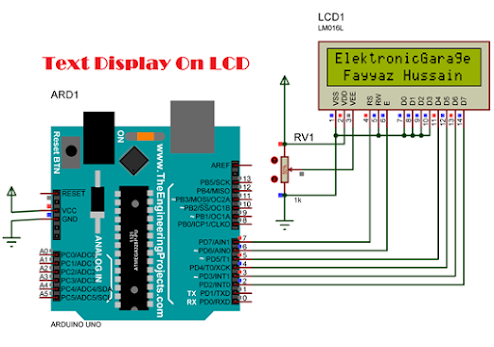
LCD 16x2 Interfacing with Arduino (Text Displaying)


LCD 16x2 Interfacing with Arduino (Text Displaying)

LCD (Liquid Crystal Display) 16x2 is used to display ASCII characters. LCD is very impressive and attractive for any Arduino Project or any controller project. We can display direct text (ASCII) Alphabets and digits on it and can display function type values also, simply there are techniques to display your text on LCD. Here we are displaying just simple text to show interfacing and simple steps in Arduino IDE coding. Arduino IDE also has built-in examples in which you can modify but have understanding when you want to use in your own project and may this built-in example not fit for that. Here we are giving you understanding.

Application:

Display Characters in ASCII format

Display text, digits, etc.

Components:

Arduino Uno

Connectors

Arduino IDE (Compiler software)

Computer for programming

LCD 16x2

Pot-meter: Use to control the contrast of LCD

Circuit:

LCD 16x2 Interfacing with Arduino (Text Displaying)
Connects are given very clear in circuit diagram but if you have any query then you can ask me.

Coding:

/// LCD Display ///

/// ElktronicsGarage1.blogspot.com ///

/*LCD D7 to D4 - Arduino Uno Pin 2-5

LCD EN - Arduino Uni pin 6

LCD RS - Arduino Uni pin 7

LCD D3 to D0 and RW and Vss Ground connected

Vdd with Vcc and VEE use to control the contrast

*/

// include the library code:

#include <LiquidCrystal.h>

// LCD PINs

const int rs = 7, en = 6, d4 = 5, d5 = 4, d6 = 3, d7 = 2;

LiquidCrystal lcd(rs, en, d4, d5, d6, d7); 

void setup() {

  // Initialize LCD 16x2

  lcd.begin(16, 2);

  }

void loop() {

  // set the cursor to column 0, line 1

  lcd.setCursor(0, 0);

  // print the number of seconds since reset:

  lcd.print("ElektronicGarage");

    delay(100);

  lcd.setCursor(0, 1);

  lcd.print(" Fayyaz Hussain ");   delay(100);

}


Read More

Monday, June 28, 2021

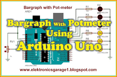
Bar graph LEDs Control with Arduino Uno


Bar graph LEDs Control with Arduino Uno

Bar-graph is the combination of LEDs in a Line that mostly use to display the level of the signal.

Applications:

We also use it to show the water, gas pressure, temperature, and light intensity levels also. Simply its general purpose use can use where you want to show / indicate the level of any measured value. It’s important so I decided to include it in this manual (which’s for beginners).

Components:

Bar-Graph:

We can use this bar graph as shown in the diagram but I have selected only 6 LEDs as bar-graph with Arduino because 6 LEDs bar-graph not available in Proteus for simulation but practically you can use this by extending the code as well.

Bar graph
Proteus Circuit
How we can use a bar graph

Circuit Diagram:

Bar graph LEDs Control with Arduino Uno

Bar graph with POt-meter using PIC Controller 


Here I am using ADC (built-in) to read the value of the pot-meter and how its works I have discussed this in a previous Project (Fading LED with Pot-meter).

As we know that 10bit ADC max value is 210 = 1024 which is divided by no of LEDs.

As  approximately

Now put the condition in coding that when the value of ADC >170 then ON 1st LED. (See in coding)

Download Code


Read More

Thursday, June 24, 2021

Arduino Project LED Chaser

Hi here is one more Cool Arduino Project for Arduino learners that is LED chaser Arduino based. I have already made the same LED Chaser project with PIC microcontroller you can visit also that too. 
In this project, I have used 6 LEDs to flash in different sequences by push button.

The component used in this project

2. LEDs 
3. Push Button
4. Resistor 1K

Circuit:


The push-button function can see in the following GIF Proteus simulation.


I am sharing here the coding in a new technique you can see. I am showing how to access the Controller ports directly in a new technique instead of a single pin for declaration in coding.

Click me for Code


Read More

Saturday, June 12, 2021

Token counter using Arduino and 7 segment Display

Token counter using Arduino and 7 segment Display
Hi here is one more interesting project Arduino based Token counter with 7 segment. 
7 segment is basically a combination of LEDs nothing more. We can connect it directly to Arduino too, but many pins will be engaged so we will use driver IC for 7 segment display. 
Now here is one more question that there are two types of 7 segment display. One is a common cathode (cathode terminal of all LEDs are common and apply +tive voltage to ON any segment). The second one is the common Anode which is the inverted version of CC. Here we are using CC 7 segment. 

Components List:
Arduino Uno
Seven Segment Display
LS7448
Push Button
LED
Token counter using Arduino and 7 segment Display
One more thing which I have used, that is the display driver IC for common cathode 74LS48. All connections are shown in the circuit diagram.

The same project I have completed with the PIC controller. 7 segment programming in MikroC for PIC is very easy but here in Arduino's case, it is very tricky so we are sharing with Arduino also.

Here is the simulation: 

Token counter using Arduino and 7 segment Display


Download Code


If you like this work then plz like comment and share.
Read More

Sunday, May 23, 2021

Current sensor ACS712 Interfacing with Arduino


Hi here one more new little project of My large Project of Home Power Management. I am reading current value using ACS712 current sensor by using Arduino Uno.
Here is little bit calculation for calibration of reading which is very simple.
So first of all we will see the datasheet of ACS712 for specifications of current sensor.

To show Vcc value

Here is important to note the mv/A value mean that sensor produce the output how many mv on 1A. See under datasheets screen shorts that 5A produce 185mv/A, 20B produce 100mv/A and 30B produce 66mv/A.
ACS712 5A ()
ACS712 20B
ACS712 30B

ACS712 Module:  

Circuit Diagram:
One more thing that this sensor give offset value 2.5v at output, So in reading we will minus this value.
Now we know first thing is that ADC of Arduino has 10 bits length. 
So Arduino will convert input into 2^10 values means 1024. So find the mini voltage on which ADC change one bit. (0000000000 to 0000000001)
= 5v/1024 = 0.004883 = 4.883mv or 
= 2.5/ 512 = 0.004883 = 4.883mv
Now 100mv/A in case of ACS712 20B
Now calculate the factor to Convert input reading into current value.
for example 100mv/4.883mv = 20.8 
after that do this 
value = analog.Read(A1) 
I (current) = value / factor (20.8)
now Display this on LCD or serial out or use in any where, where you want.

See the Simulation here:


Download the code and Proteus simulation here: Github link

Click me for code

If you like my work then denote my effort
at JazzCash 03455913812


Read More

Tuesday, May 11, 2021

Arduino LED light Control through Potentiometer


Here in this project we will combine two projects one is fading of LED light and second one is reading the analog value of pot-meter. Then resultant we will control the LED light with variation in the value of pot-meter.

Application:

We can control the speed of DC motor.

We can control the position of solenoid valve.

And some other related to this application

Circuit diagram: 


Calculation of factor:

A little bit calculation to manage the values of Analog read with PWM output.

Analog reading pin internally have 10bit of ADC so it means that

Vin (max) = 5v

Converted into 10bit digital means 0000000000 to 1111111111 from 0 to 1024

 2^10 = 1024

And PWM range is 0 to 255 so simple to fine the factor

Factor = 1024/255  = 4.0156 round off 4.02

Simulation of PICSimLab:


Download the code

If you like my post then like share and comment if any Question
Read More

Important Artical

Popular Articals

Total Page views in This Month

© 2019-20 Electronics Garage. Designed by Uzma 0101 & Distributed by elektronicsgarage1.blogspot.com