What is a Water level Indicator?
A water level indicator is a device used for an indication of the water level in the water tank. So that the operator of the water pump knows the level and operates the motor to fill it again or take any particular required action.
Application of Water Level Indicator
Mostly this device is used as an assignment for Digital Logic Design students to complete. But this is very useful at the domestic level as well as for small industry for to automate the water level of water tanks.
Water level indicator circuit story
Here we have used only the logic gates game to complete this Project. It was very complicated to make the logic in the scenario of the water tank.
look at the scene here
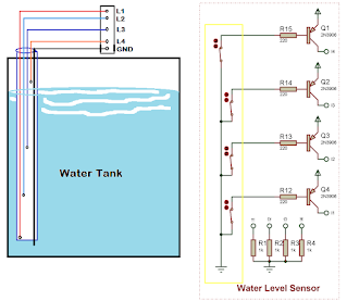
Water Level Sensor
we have used PVC pipe in the tank and adjusted wires according to the diagram of the tank. all wire connections are terminated at PNP Transistor 3906 Q1, Q2,Q3 and Q4 base terminal through resistor.
Water level sensor principle
GND wire is in the bottom of the tank and other wires are at different water levels. when any level wire connects with GND through water then that PNP transistor switches ON and current flow through the emitter to the collector Max voltage drop across the 1k ohm resistor at the collector.
when the water level drops from the wire approximately 0 voltage appears across a 1k ohm resistor.
So now it's simple to make the logic that could be in the form of DLD, any Microcontroller, Arduino, etc.
So here we are making the logic of the water tank.
When the Tank is at 0% (empty) the Motor will start using NAND Logic and stop when the tank will touch 100% (Full).
The motor is not only dependent on the NAND gate because if the level drops from 100% then again motor will start but we want to ON the motor again at 0%. So we apply NAND output at the input of D Flip Flop. Now the rising edge is required to pass the logic.
For the D-FF clock signal we use the AND gate and NOR gate at the same inputs (Table of all Gates is given above Table)
see the working
At 0% NAND gate sends logic 1 at D and at the same time, XOR will send an enable rising signal to D-FF So the output of D-FF will be high due to which the motor starts by the motor driver circuit. The motor will remain ON until the status of D-FF is changed.
So Now when the tank reaches 100% of the level the NAND gate sends 0 at D-FF and again XOR gate will send the rising signal at the clock and D-FF will transfer 0 at output and the motor will stop until again status of D-FF changes. The status of D-FF will change at 0% or at 100%.
ALARM: The alarm will start by NOR Gate Output because here water tank is at 0%.
Motor Driver Circuit
D-FF output terminated at R5. An NPN transistor 3904 uses BJT as a Switch to operate the SPDT relay to drive the motor.


No comments:
Write commentsI am very thankful for your precious time