Interface 7 Segment 4x1 with PIC controller using PIC controller
7 Segment display use to display the values in form of
digits. So it’s important to learn 7 segment and how to drive single 7 segment using different controllers and that code programs in different compilers. The basic
Concept remain same. So here we are going to drive 4 digit 7 segment using PICcontroller and compile it working code in MikroC pro for PIC.
After coding compilation its important to test it on circuit
so we use Proteus 8.15 for simulation.
For types of 7 segments see this topic:7 Segment Interfacewith PIC Microcontroller as Up Counter
4 digit 7 segment in Proteus:
PINOUT of 4 digit 7 segment:
Example to Display the 4 digits value:
1234 is value for example:4 is at unit position
3 is at 10th position
2 is at 100th position and
1 is at 1000th position
When we will display 4 then we select unit digit by
using pin DG1 and send the data of 4 (in form of binary which drive the 7
segment)
See this table:
|
Digit |
Dp |
G |
F |
E |
D |
C |
B |
A |
Hex |
|
0 |
0 |
0 |
1 |
1 |
1 |
1 |
1 |
1 |
0x3F |
|
1 |
0 |
0 |
0 |
0 |
0 |
1 |
1 |
0 |
0x06 |
|
2 |
0 |
1 |
0 |
1 |
1 |
0 |
1 |
1 |
0x5B |
|
3 |
0 |
1 |
0 |
0 |
1 |
1 |
1 |
1 |
0x4F |
|
4 |
0 |
1 |
1 |
0 |
0 |
1 |
1 |
0 |
0x66 |
|
5 |
0 |
1 |
1 |
0 |
1 |
1 |
0 |
1 |
0x6D |
|
6 |
0 |
1 |
1 |
1 |
1 |
1 |
0 |
1 |
0x7D |
|
7 |
0 |
0 |
0 |
0 |
0 |
1 |
1 |
1 |
0x07 |
|
8 |
0 |
1 |
1 |
1 |
1 |
1 |
1 |
1 |
0x7F |
|
9 |
0 |
1 |
1 |
0 |
1 |
1 |
1 |
1 |
0x6F |
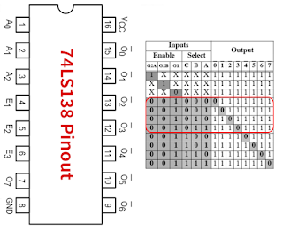
And we are using decoder 74LS138 Mux IC to select the 7
segment digits and saving the pins of controller. We are using Just for 4
output control red blocked area of the table.
When we will display 3 then we select 10th
digit by using pin DG2 and send the data of 3.
When we will display 2 then we select 100th
digit by using pin DG3 and send the data of 2.
When we will display 1 then we select 1000th digit by using pin DG4 and send the data of 1.
Circuit Diagram:
/// Multiplexed 7 Segments ///
/// Eleltronics Garage     ///
/// By: Fayyaz Hussain     ///
///   29 Oct, 2023         ///

int count=0;
void counter();

int up_pr=0,down_pr=0,digit1=0,digit2=0,digit3=0,digit4=0;

// Array of 7 Segment display decoder
unsigned int seg_num[]={0x3F,0x06,0x5B,0x4F,0x66,0x6D,0x7D,0x07,0x7F,0x6F};

sbit up at RD4_bit;  // Up count Button
sbit down at RD5_bit;// Down count Button
sbit rst at RD6_bit; // Reset to 0 button

sbit A at RD0_bit; // Decoder 74LS138 IC INPUT A,B
sbit B at RD1_bit; //

void main() {
TRISB=0x00;
TRISD=0xF0;
PORTB=0x00;
PORTD=0x00;

while(1)
     {// UP counting using Falling Edge
      if(up==1){up_pr++;}
      if(up==0 && up_pr>=1){count++;up_pr=0;}

      // DOWN counting using Falling Edge
      if(down==1){down_pr++;}
      if(down==0 && down_pr>=1){if(count>0){count--;}
                               down_pr=0;}

      if (rst==1){count=0;} // Reset the counter

counter(); // function to define digits position
     // Unit position Digit
     B=0;A=0;
     PORTB=seg_num[digit1];
     Delay_ms(2);
     // 10th position digit
     B=0;A=1;
     PORTB=seg_num[digit2];
     Delay_ms(2);
     // 100th position Digit
     B=1;A=0;
     PORTB=seg_num[digit3];
     Delay_ms(2);
     // 1000th position Digit
     B=1;A=1;
     PORTB=seg_num[digit4];
     Delay_ms(2);
     }
}

void counter()
{
digit1 = count%10;
digit2 = (count%100)/10;
digit3 = (count%1000)/100;
digit4 = count/1000;
}


Wah...nice
ReplyDelete